Composites & multilayer materials
Controlled decomposition of an organic matrix to facilitate recovery of metallic, mineral, fibrous or other solid fractions intended for downstream processing.
CFI Systems designs, manufactures and integrates chamber pyrolysis furnaces for batch or multi-batch thermal processing. The objective is to decompose or remove an organic fraction in a controlled way so that solid constituents can be released, separated or prepared for downstream recovery.
Sizing starts with the real product: load geometry, thermal behaviour, gas release, throughput, handling method, emission constraints and interfaces with upstream and downstream equipment.
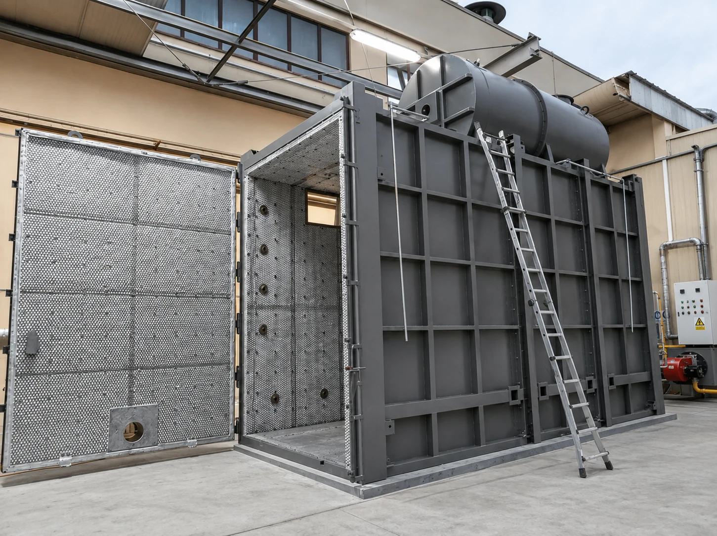
CFI Systems targets complex products and materials where an organic fraction must be thermally decomposed or removed in order to release solid constituents, prepare mechanical separation or improve a downstream recycling step.
The furnace is defined from the real load: dimensions, mass, polymer or organic-binder content, gas release, contaminants, sensitivity of the fractions to be recovered and the required industrial throughput.
Controlled decomposition of an organic matrix to facilitate recovery of metallic, mineral, fibrous or other solid fractions intended for downstream processing.
Processing of structured products containing resins, adhesives, encapsulants or polymer elements when thermal removal can release useful components without systematic pre-shredding.
Applications requiring progressive thermal delamination before sorting, separation or recovery of layers and constituents with different material properties.
Decomposition of encapsulation polymers to facilitate recovery of glass, silicon and metallic fractions before downstream separation and refining stages.
Study of structured industrial loads or products conditioned on supports where the objective is to remove an organic fraction while recovering a usable solid material downstream.
Development of a specific batch cycle when the product, its geometry or the plant layout require a chamber, handling system and gas-treatment line designed around the process.
CFI Systems positioning: chamber pyrolysis furnaces for batch or multi-batch loads. Thermal recipes, loading, afterburning and flue-gas treatment are defined project by project.
Carts, rails, technical access, combustion equipment and building interfaces are integrated from the design stage to simplify batch operation.
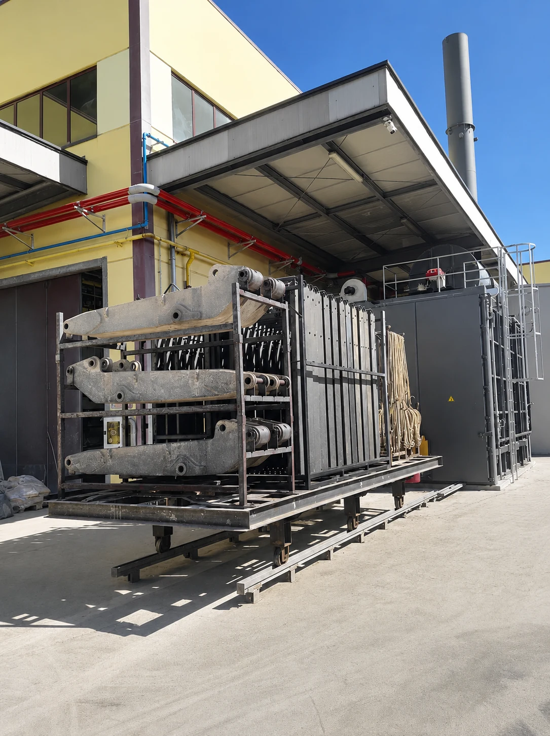
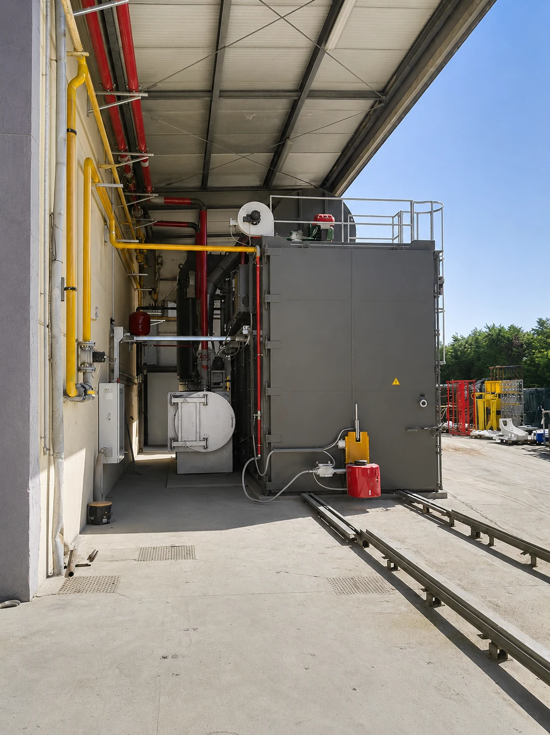
The thermal cycle is designed to decompose or volatilise an organic fraction under controlled conditions. Temperature, heating rate, dwell times, air renewal, oxygen level and any required inerting are defined according to the product and the separation objective.
The released gases are collected and routed to an afterburning stage and, where required, to a cooling, neutralisation and filtration system adapted to their composition.
CFI Systems focuses on chamber furnaces for discrete loads, racks, baskets or dedicated supports. Plant capacity can be increased through chamber sizing or by operating several chambers in parallel.
One chamber and one independent cycle for structured or bulky loads, or applications requiring high recipe flexibility.
Several chambers operating in parallel with common handling arrangements and, depending on the project, shared peripheral equipment.
A pass-through chamber can be studied to separate loading and unloading areas and improve forward material flow through the plant.
Rails, conveyors, transfer carts, racks or baskets are selected according to load mass, dimensions and upstream/downstream interfaces.
Useful volume, heat circulation, door arrangement, insulation and instrumentation are sized from the product and required throughput.
The layout can allow future addition of chambers or peripheral equipment as the industrial project increases in capacity.
The heating method is selected according to required power, control accuracy, site energy constraints and product behaviour. The design aims for uniform heat distribution and zone control where this improves management of gas release.
When the load must be protected from direct flame contact, burner arrangement and hot-gas circulation are engineered accordingly.
The nature and release rate of organic compounds directly determine the afterburning stage and the downstream flue-gas treatment system. Sizing is therefore based on the thermal recipe and the material balance.
Depending on product composition, downstream treatment can include gas cooling, acid-gas neutralisation, dust filtration and emissions monitoring.
Photovoltaics illustrates the role of the furnace well: the material is not simply destroyed; the polymer fraction is thermally treated to facilitate access to solid constituents that can then be separated and recovered in downstream stages.
Removal of peripheral elements where required and organisation of modules or laminates according to the plant flow.
Racks, baskets or supports designed for handling and suitable heat circulation around the products.
Controlled thermal recipe to decompose encapsulants and release the solid constituents.
Thermal treatment of gases sized according to the real polymer release during the cycle.
Cooling, neutralisation and filtration adapted to gas composition and site requirements.
Interface with mechanical sorting and processes used to recover glass, silicon and metallic fractions.
CFI Systems focuses on the thermal package and its interfaces: chamber furnace, associated handling, afterburning, flue-gas treatment, automation and integration with upstream and downstream equipment.
Hot gases leaving the afterburning stage can represent a significant energy source. Recovery is studied according to available temperatures, cycle frequency, site demand and the constraints of the flue-gas treatment system.
The objective is to recover useful energy without compromising process stability or environmental performance.
A pyrolysis cycle can include very different gas-release phases. Safety therefore relies on instrumentation, automatic sequences and consistent sizing of the chamber, afterburning stage and extraction system.
The level of inerting, cooling devices, bypasses or other safe-state functions are defined through the risk analysis and according to the material being processed.
The control system coordinates loading, doors, heating, temperature zones, air, extraction, afterburning, flue-gas treatment, cooling and safety functions.
Heating ramps, dwell times, setpoints and sequences tailored to each product family.
Temperatures, pressure, oxygen, flows and measurements required to operate the process.
Process overview, alarms, trends, equipment status and diagnostic support.
Cycle records used to compare batches, improve settings and document operation.
CFI Systems can assess existing equipment to identify potential improvements to automation, heating, heat circulation, sealing, handling, afterburning, filtration, heat recovery or safety.
The modernisation scope is defined from the actual condition of the installation and the compatibility of retained equipment with the new operating requirements.
CFI Systems does not intend to freeze a model range before the requirement has been characterised. The study begins with the real load, the target thermal recipe, gas release, handling flows and downstream treatment.
Mass, dimensions, composition, organic fraction, contaminants, variability and loading supports.
Delamination, release of a solid fraction, preparation for sorting or another thermal-separation objective.
Temperatures, heating ramps, dwell times, cooling and opening/unloading conditions.
Chamber, number of furnaces, handling, afterburning, filtration, extraction and heat recovery.
Mechanical systems, flue gas, electrical systems, automation, line interfaces, testing and training.
Analysis of cycles, energy use, idle time, maintenance and future multi-batch expansion possibilities.
Photovoltaics is an important application, but it does not define the entire offer. CFI Systems more broadly targets complex products where an organic fraction must be thermally treated to enable downstream separation or material recovery.
A photovoltaic panel, composite, multilayer laminate or technical assembly does not require the same heat circulation, cycle duration or flue-gas treatment strategy.
Geometry, mass and composition determine chamber sizing.
Recipes, zoning and heat circulation govern organic release.
Afterburning, cooling, neutralisation and filtration are sized together with the furnace.
Loading, unloading and material separation are part of the overall integration.
CFI Systems focuses on batch and multi-batch chamber furnaces sized around structured loads and industrial line integration.
It is a thermal system in which a load is processed by batch according to a defined recipe in order to decompose or remove an organic fraction. Air or oxygen levels are controlled according to the application, and the generated gases are collected and treated separately.
Incineration primarily aims to destroy waste thermally through oxidation. In the CFI pyrolysis approach, thermal treatment is used to modify or remove an organic fraction so that solid constituents can be released or prepared for recovery, with separate treatment of the gases generated.
Thermal cleaning primarily aims to clean and recover a part, tool or metal load by removing paint, resin, oil or polymer. The industrial pyrolysis approach presented here is more directly integrated into a separation or material-recycling chain for a complex product.
Yes. Thermal treatment can decompose encapsulation polymers to facilitate subsequent separation of glass, silicon and metallic fractions. The furnace, afterburning stage and flue-gas treatment system must be sized together.
Yes. The intended positioning is based on batch chamber furnaces, with the possibility of arranging several chambers in parallel when throughput or process availability justifies it.
Yes, where the plant benefits from forward material flow with separate loading and unloading areas. Relevance depends on layout, safety and handling requirements.
Yes, depending on required power and project constraints. Heating can be electric or gas-fired; the priority is to achieve the control accuracy, uniformity and thermal dynamics required by the cycle.
They are collected and routed to an afterburning stage sized according to gas flow and composition. Downstream treatment can then include cooling, acid-gas neutralisation, dust filtration and extraction.
Yes, when the thermal profile, number of cycles and site demand justify it. Recovered heat can be used to preheat a fluid or utility gas, produce hot water or meet other thermal needs.
Yes, following an audit. The scope can include heating, zoning, automation, doors, handling, afterburning, flue-gas treatment, heat recovery, instrumentation and safety systems.
CFI Systems also develops cremation systems, incineration systems, thermal cleaning & paint stripping ovens, as well as solutions for precious-metal recovery, combustion, flue-gas treatment and energy recovery.
Explore all our solutionsPhotovoltaic panels, composites, laminates, technical assemblies, multilayer products, structured industrial residues, new installation or retrofit: CFI Systems studies the chamber furnace and its interfaces from the real load and the separation objective.